Material
Body aluminium.
Piston steel.
Piston steel.
Version
Body silver anodised.
Piston hard chrome-plated
Piston hard chrome-plated
Show more
Show less
Description
Material
Body aluminium.
Piston steel.
Piston steel.
Version
Body silver anodised.
Piston hard chrome-plated
Piston hard chrome-plated
Note
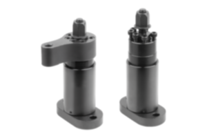
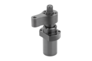
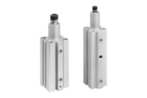
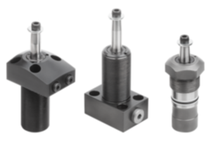
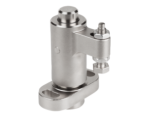
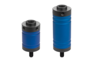
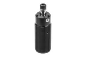
Screw-in pneumatic swing clamps with flange find use where low clamping forces suffice and where the clamping point has to be cleared to enable placing or removing the workpiece.
The design enables space saving installation. The screw-in bolt can be used to adjust the height of the swing clamp. The clamp is suitable for a sunken mounting in a fixture. The compressed air port for the swing clamp is in the flange.
Due to the double-acting function of the clamp, pressure is used to move the piston downwards and upwards.
The total travel of the swing clamp consists of the swing travel and the clamping travel. At the start of the clamping process, the clamping arm performs a 90° swing movement. When this movement is completed, the linear down clamping travel is carried out. The workpiece must only be clamped using the clamping travel.
The swing clamp must not be constrained in its swinging action. F1 = at 6 bar max. permitted operating pressure.
The screw-in swing clamp with flange can be fastened from above or below using a DIN 70852 slotted round nut. Another option is to fasten the swing clamp to the fixture from above using four cap screws.
The swing clamp must only be operated using lubricated air.
The fastening holes in the flange have the same dimensions as those in the threaded flange K1820.
The screw and the lock washer for fastening the clamping, which is available as an accessory, are supplied.
Clamping arm and slotted round nut are not supplied.
Drawing reference
1) Clamping
2) Releasing
3) Swing travel
4) Clamping travel
5) Relaxed
6) Tensioned
7) Left swinging
8) Right swinging
2) Releasing
3) Swing travel
4) Clamping travel
5) Relaxed
6) Tensioned
7) Left swinging
8) Right swinging
Accessory
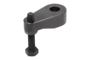
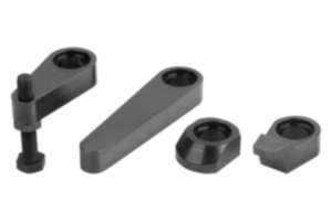
K1816 Clamping arm for swing clamp.
DIN 70852 slotted round nut.
DIN 70852 slotted round nut.
Important note on downloading CAD models
You must log in before you can download our CAD models. If you have not yet created an account, please register under "My account" (right-hand side of the screen) and follow the instructions.


